


Hydraulic Solenoid Valve
Safe Load Holding & Motion Control – Counterbalance Check Valve A counterbalance check valve is normally a closed pressure valve. It is used with cylinders to support a counterweight or a potentially overrunning load. In certain processes, uncontrolled operation can occur. A counterbalance check valve prevents this. It is a hydraulic system pressure control valve that acts as a safety device. It stops the movement of a loaded actuator without the application of additional pressure from the system power unit. Most counterbalance valves are used to prevent a weight from falling uncontrollably. These valves maintain backpressure so that a load cannot drop. A counterbalance check valve allows the downward movement of a load supported by a cylinder only when the system pump is operating. Flying Bull Electronics is a professional manufacturer specializing in solenoid valve coils, special solenoid valves, and automation supporting components. Most of our products are used in pneumatic, hydraulic, and other automation control industries. Our products are trusted by many internationally renowned brands. Why Choose Flying Bull Counterbalance Check Valves? Advanced Equipment – Over 20 years of design and development experience. Focus on auto solenoid valves, sensors, and engineering machinery solenoid valves. Rich Experience – Business philosophy: “expert quality, global trust.” Purpose: “pursuing quality, never ending.” High Quality – R&D center, measurement lab, testing lab, and chemical analysis room. New high‑tech products launched every year. Professional Team – Strong R&D capabilities, first‑class talent, strict quality control, scientific management, and perfect service. Benefits of Counterbalance Check Valves 1. Safety – By preventing uncontrolled load movement, counterbalance check valves significantly enhance safety for operators and bystanders. 2. Precision Control – They enable precise control over cylinder movement, even under heavy loads, leading to smoother operation and improved accuracy. 3. Enhanced Productivity – By minimizing downtime due to uncontrolled movement, counterbalance check valves contribute to increased productivity and efficiency. 4. Reduced Wear and Tear – Controlled movement protects the cylinder and other components from excessive stress, extending equipment life and reducing maintenance costs. How Counterbalance Valves Work A counterbalance valve is a combination of a pilot‑operated relief valve and a reverse free‑flow check valve. Raising the load – The free‑flow check allows oil to flow unrestricted into the cylinder to raise the load. Holding the load – When the control valve shifts to neutral, load‑induced pressure forces the check valve closed. As long as this pressure is below the relief setting, the load stays in place. Lowering the load – When the control valve shifts to lower, pressure on the opposite side of the cylinder acts on the pilot port. This pressure combines with load‑induced pressure to overcome the relief setting. The relief valve opens, allowing controlled lowering. When the control valve shifts back to neutral, pilot pressure is lost, and the relief valve closes – holding the load again. A counterbalance valve has a modulating characteristic that is a function of both load pressure and pilot pressure. This creates an inverse pilot ratio: Light loads require more pilot pressure. Heavy loads require less pilot pressure. During normal operation, the adjustable spring force of the relief function is overcome by a combination of load‑induced pressure and pilot pressure. The higher the load‑induced pressure, the less pilot pressure is required – and vice versa. This modulation gives the counterbalance valve smooth operational control throughout a dynamic load curve. Counterbalance Valve Application A counterbalance valve is applied to create backpressure or cushioning pressure on the underside of a vertically moving piston. This prevents a suspended load from free‑falling due to gravity while it is being lowered. Lowering operation – The pressure setting on the counterbalance valve is set slightly higher than the pressure required to prevent the load from free‑falling. Due to this backpressure, the actuator piston must force down when the load is being lowered. This increases pressure, raises the spring‑opposed spool, and provides a flow path to discharge exhaust flow to the tank. The spring‑controlled discharge orifice maintains backpressure during the entire downward piston stroke. Lifting operation – The valve is normally closed. Flow in the reverse direction (from port B to port A) cannot occur without the reverse free‑flow check valve. When the load is raised again, the internal check valve opens to permit flow for cylinder retraction. Suspension (prolonged holding) – When the valve is held in suspension, the valve remains closed. Its pressure setting must be slightly higher than the pressure caused by the load. Spool valves tend to leak internally under pressure. For loads that must be held for a long time, use a pilot‑operated check valve in addition to the counterbalance valve. How to Set a Counterbalance Check Valve The relief function has two important set points: the cracking pressure (where the valve starts to open) and the reseat pressure (where the valve closes). The reseat pressure is generally about 85% of the cracking pressure. For this reason, counterbalance check valves are normally set at 1.3 times the maximum load pressure. This ensures that the valve will reseat under the heaviest load conditions. Some manufacturers may specify a setting of 1.5 times the maximum load pressure if that value is less than 2000 PSI (138 bar). Counterbalance check valves are available in a variety of pilot ratios: Lower pilot ratios (e.g., 3:1) provide better motion control and stability but are less efficient and may create excess heat. Higher pilot ratios are more efficient but may have less stable control. Pilot ratios of 3:1 or 4.5:1 are typically selected for load‑holding cylinder applications, as they provide a good balance between performance and efficiency. Materials Used in Counterbalance Check Valves PVC & CPVC – Corrosion resistance, flexibility, higher temperature rating for CPVC. Bronze & Copper – Low/medium pressure, corrosion resistance, easier to work. Cast Iron & Ductile Iron – Excellent corrosion resistance, ductile iron is stronger and bendable. Stainless Steel – Corrosion resistance, withstands harsh and chemical applications. Cast Steel – Resists sudden shocks without deformation or breakage. Polypropylene (PP) & PVDF – Exceptional corrosion resistance, acid/solvent resistance. Flying Bull’s counterbalance check valves are 100% brand new, manufactured in Zhejiang, China, and backed by a 1‑year warranty. Delivery takes 5–7 working days. Choose Flying Bull for safe load holding and precise motion control.
Product Introduction
Company Profile
Automotive solenoid valves and sensors are our company's featured products. At the same time, our company is also a professional manufacturer specializing in the production of solenoid valve coils and special solenoid valves and other automation supporting components. Most of our products are used in pneumatic, hydraulic and other automation control component industries. At present, our products have been used by many internationally renowned brands and are deeply trusted by our customers.
Why Choose Us
Advanced Equipment
Flying Bull (Ningbo) Electronic Technology Co.,Ltd has an excellent team with more than 20 years of experience in design and development, focusing on the design, development and production of auto solenoid valve and sensor, engineering machinery solenoid valve and sensor.
Rich Experience
The company adheres to the business philosophy of "expert quality, global trust" and the business purpose of "pursuing quality, never ending".
High Quality
Quality is always our Flying Bull's unchanging concept. The company has established a research and development center, measurement room, laboratory, and chemical analysis room, and launches a number of high-tech products every year.
Professional Team
The company has strong R&D capabilities to lay a good foundation for the development and cooperation of new products for customers. First-class talents, advanced equipment, strict quality control system, scientific management, perfect service, and strong R&D capabilities, let us work together to become industry pioneers and win an unlimited future.

The main function of the metering unit 0928400568 is to accurately control the amount of pressurized fuel entering the pump when the engine is running, according to the difference between the fuel injection rate of the injector calculated by the ECU (electronic control Unit) and the current and target rail pressure.

SV08-30 products are widely used in steel, metallurgy, petrochemical, aerospace, shipbuilding, coal, cement, electric power, automobile, engineering machinery, food, forestry, textile, leather, paper and other industries.

The Hydraforce Solenoid Valve Replaced DF10-05 normal opening pressure is 1.6 bar, and other opening pressures can also be customized for production, such as 2.6 bar and 4 bar.

Hydraulic Threaded Cartridge valve is a multifunctional composite valve with the basic components of cartridge valve (spool, sleeve, spring and seal ring) inserted into a specially designed and processed valve body, and equipped with a cover plate and pilot valve.
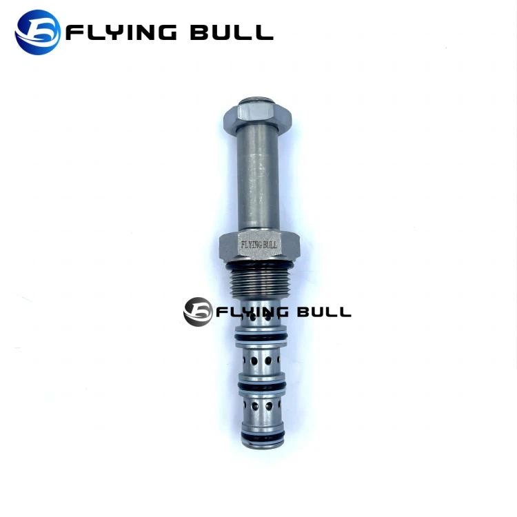
Cartridge valves are usually switched on and off manually or electrically. The manual mode generally uses manpower, hydraulic, pneumatic and other forces to drive the stem and spool.

Directional control valve. It is well suited for use in specialized low-pressure pilot systems or power shift transmission control. The coil is an integral part of the valve and is not serviceable.

Hydraulic cartridge solenoid valve SV10-41 Construction machinery parts. Upon receiving the close command from the starting switch, the loader transmission's solenoid valve necessitates the disconnection of power to its coil.

NEW HOLLAND/CASE IH Solenoid Valve 87472229. When the closing solenoid valve of the loader transmission is closed by the starting switch, the power supply to the solenoid coil should be cut off, so that the valve plate closes the oil circuit through the spring force, thus effectively shutting down the engine.

The underground setting is inherently hazardous, harboring explosive gas mixtures inclusive of methane and coal dust. Consequently, the solenoid valve 206-60-51132 must embody explosion-proof capabilities, forming a barrier against any potential internal explosion from permeating the ambient environment.
What is Hydraulic Solenoid Valve
A hydraulic solenoid valve is a solenoid controlled directional valve used in a hydraulic system for opening, closing or changing the direction of flow of the liquid. The valve operates with a solenoid, which is an electric coil wound around a ferromagnetic core at its center. The valve consists of various chambers also called ports. The solenoid is used for sliding the spool within the valve, opening or closing the ports. The spool is the cylindrical component which serves the function of the valve by either blocking or allowing the flow of liquid through these ports, depending upon its position.
Benefits of Hydraulic Solenoid Valve
Fast and Efficient
The response of the valve after it is energized is usually very fast. Remember that a solenoid valve only takes a few milliseconds to respond, while a pilot valve can react within tens of milliseconds.
Energy Saving
A well-designed manual hydraulic solenoid valve consumes very little power, so it can save a lot of energy. After power is applied, the valve position switches automatically, and it does not require any additional electricity to maintain that position.
Easy Control of Leakage
Internal and external leakage often compromises the safety and efficiency of the valve. In other valves, the valve stem is controlled electrically or pneumatically, which means that dynamic seals can leak.
Simple and Easy to Use
The valve structure is very simple, easy to install and maintain. Compared with other regulating valves, they are also relatively cheap.
Low Maintenance
Since hydraulic solenoid valves have few moving parts, they are unlikely to fail and therefore do not require a lot of maintenance. This simple design means that you can repair and clean them very easily, reducing downtime.
Type of Hydraulic Solenoid Valve
Direct-Acting Solenoid Valves
In a direct-acting hydraulic solenoid valve, the solenoid directly opens or closes the valve. When electricity flows through the solenoid coil, it generates a magnetic field that moves the plunger, thus opening or closing the valve. Direct-acting solenoid valves are reliable and quick-acting, but they are usually limited to smaller flow rates due to the power required to move the plunger directly against the hydraulic pressure.
Pilot-Operated Solenoid Valves
Pilot-operated solenoid valves, on the other hand, use the hydraulic pressure difference to open or close the valve. They are equipped with a small pilot valve, controlled by the solenoid, which then controls the main valve. Pilot-operated valves are efficient for larger flow rates but are slower to actuate and more complex in design than direct-acting valves.
Hybrid Solenoid Valves
There also exist hybrid solenoid valves that combine the principles of direct-acting and pilot-operated solenoid valves, leveraging the benefits of both types. They can handle higher flow rates and respond quickly.
Hydraulic Solenoid Valve Working Principle
The working principle of a hydraulic solenoid valve is centered on the fundamental concept of electromagnetism. As electricity passes through the solenoid coil, it creates a magnetic field. This magnetic field then moves a ferromagnetic plunger located within the coil, thus opening or closing the valve.
When the electrical current to the solenoid is turned on, the magnetic field causes the plunger to move and open the valve. Conversely, when the current is turned off, the magnetic field collapses, and a spring forces the plunger to return to its original position, closing the valve. This ability to rapidly switch the state of the valve from open to closed, simply by applying or removing an electrical current, is what makes the these valves such an effective control device in a hydraulic system.
One critical aspect of a hydraulic solenoid valve's operation is the pressure balance. For the valve to function properly, there must be a balance between the hydraulic pressure acting on the valve and the force exerted by the solenoid and the spring. This is why the specifications of the solenoid, such as voltage and current, as well as the hydraulic system's pressure, are essential parameters when selecting the right valve.
Applications of Hydraulic Solenoid Valves
Hydraulic solenoid valves are integral components in an array of industries due to their versatility and functionality. They play a pivotal role in industrial automation, providing precise control over fluid power in numerous applications.


Manufacturing and Industrial Applications
Hydraulic solenoid valves are often utilized in automated assembly lines and process control systems. They facilitate the control of machinery and equipment, enabling automatic start-stop functions and regulating fluid flow rates. Such usage is critical in industries like food processing, textiles, and pharmaceutical manufacturing.
Automotive Industry
Hydraulic solenoid valves are integral to automatic transmission and power steering systems. They regulate fluid flow, thereby controlling gear shifts and steering mechanisms. Similarly, in braking systems, they help modulate the hydraulic pressure, improving safety and reliability.
Hydraulic solenoid valve applications in the automotive industry
In the realm of vehicle manufacturing, hydraulic solenoid valves play a crucial part in controlling the complex network of hydraulic systems that make up an automobile. They function as reliable switchgear, seamlessly shifting between different states to facilitate the operation of various vehicle systems like transmission, steering, and braking. For instance, they assist in the smooth operation of the convertible roof mechanism in luxury cars by precisely controlling the flow and pressure of the hydraulic fluid. Similarly, they regulate the hydraulic suspension systems in heavy-duty vehicles ensuring a smooth and stable ride.
HVAC
Another notable application of hydraulic solenoid valves is in heating, ventilation, and air conditioning (HVAC) systems. Here, they control the flow of refrigerant, thereby influencing the cooling or heating process. This ensures optimal indoor climate control and energy efficiency.
Medical
The realm of medical equipment is not left untouched by these valves. They find their way into devices like dialysis machines and ventilators, where precise fluid control is paramount.
The hydraulic solenoid valve has a cavity sealed shut with through-openings on various positions, each gap interfaces with various oil funnels. A plunger is amidst impermeable, and two solenoids on the two sides of a plunger. When one of the solenoids loops is charged, the valve will move to a similar side. In a word, the development of pressure-driven solenoid is the way to begin or close different oil outlets.
In the meantime, the oil supply gap is constantly open, water-driven oil enters distinctive oil pipes, and utilized oil strain to push oil chamber cylinder, position drive position pole, which drives the mechanical gadget.
The hydraulic valve essentially controls the machine by controlling the on-off control of solenoid. In hydraulic solenoid valve frameworks, the component that used to control and modifies the hydraulic framework working weight, liquid stream size, and liquid bearings is called a pressure-driven control valve. Water driven control valves are the power components of hydraulic solenoid frameworks that control the on, off, a directional move of pressure-driven official components and alter water-powered framework moving pace and yield torque through the control and modify of the weight, stream, headings of water-powered working liquids.
Hydraulic Solenoid Valves A Wiring Diagram Guide
Hydraulic solenoid valves play a critical role in controlling the flow of hydraulic fluids in various industrial applications. They are electromechanically operated valves that control the direction, flow, and pressure of the hydraulic fluid. To properly wire and install a hydraulic solenoid valve, it's essential to understand its wiring diagram.
1. Understanding the basic components: Before diving into the wiring diagram, it's important to familiarize yourself with the basic components of a hydraulic solenoid valve. These include the solenoid coil, the plunger, the valve body, and the ports for fluid flow. The solenoid coil is the electromagnet that moves the plunger to open or close the valve ports.
2. Interpreting the wiring diagram: The wiring diagram of a hydraulic solenoid valve typically consists of symbols and lines that represent different electrical connections. It shows how the solenoid coil and other components are connected to power sources, ground, and control switches. The diagram also indicates the direction of fluid flow and the positions of the valve ports.
Power supply connections: The wiring diagram will indicate the power supply connections for the solenoid coil. This includes the positive and negative terminals of the power source, typically a DC voltage.
Ground connection: The diagram will show the ground connection for the solenoid coil. This ensures a complete circuit for the electrical current to flow.
Control switches: If the solenoid valve is controlled by switches or other electrical devices, the wiring diagram will depict the connections between the control switches and the solenoid coil. This allows for manual or automated control of the valve.
Fluid flow direction: The diagram will indicate the direction of fluid flow through the valve. This helps in understanding how the valve will behave when it is energized or de-energized.
Valve port positions: The diagram may include symbols or labels that represent the different positions of the valve ports. This helps in understanding the valve's functionality and its intended use in specific hydraulic circuits.
The design of a hydraulic solenoid valve is intricate and tailored for controlling fluid flow with precision. This type of valve integrates electrical and mechanical components to regulate the direction, pressure, and flow rate of hydraulic fluid within a system. Central to its design are the solenoids-electromagnetic coils that, when energized, generate a magnetic field capable of moving the valve's plunger or armature. The interaction between the current's intensity in the coil and the spring force determines the plunger's position.
Within the solenoid valve, carefully machined passageways control the travel path of hydraulic fluid. The unit houses spools that slide to block or open these channels; their movement is dictated by the solenoid action resulting from electrical signals sent by a control system. Each variation in design caters to specific functional requirements – whether it be simple on/off tasks or complex directional control needed in various applications.
Materials for constructing hydraulic solenoid valves are selected based on properties like strength, durability, and resistance to corrosion. Commonly used materials include stainless steel, brass, and thermoplastics. Sealing components play an essential role as well; they must ensure leak-proof operation under high pressure while also accommodating varying temperatures.
Additionally, relieving structures such as notches or grooves may be incorporated into designs to manage pressure surges and prevent damage during abrupt shifts in flow. Focusing on precise tolerances is key in manufacturing these valves due to their tight-seal requirements expected for reliable performance.
How to Maintenance Hydraulic Solenoid Valve
Preparation
First, make sure that the hydraulic solenoid valve is powered off to prevent accidental startup. Then, release the pressure in the hydraulic solenoid valve to ensure that the system is in a static state. Doing so can not only protect the equipment but also ensure personal safety. Next, prepare the necessary tools and materials. Tools include wrenches, screwdrivers, cleaning brushes, etc.; materials include detergents, lubricants, sealants, etc. Tools and materials must be complete so that
you can be at ease when cleaning and maintaining.
Cleaning the hydraulic solenoid valve
When cleaning the hydraulic solenoid valve 4V320-08, you must be careful and meticulous. First, clean the hydraulic solenoid valve housing with a detergent to remove dust and oil on the surface. Then, open the hydraulic solenoid valve and clean the internal valve core, valve seat and air path. Be careful not to let the cleaning agent enter the solenoid coil to prevent damage. lf the valve core or valve seat is found to be worn, it must be replaced in time.
Check the solenoid coil
Check the solenoid coil to ensure that it is intact. Measure the resistance value of the coil to see if it meets the specified value. If the coil is damaged or the resistance does not meet the requirements, it must be replaced in time. The coil is the heart of the hydraulic solenoid valve and must be taken good care of.
Lubrication and sealing
After cleaning, apply an appropriate amount of lubricating oil to the valve core and valve seat to ensure that they move smoothly. Next, check whether the sealing ring is intact and replace it with a new one if necessary to ensure the sealing performance. Lubrication and sealing are key steps to ensure the normal operation of the hydraulic solenoid valve.
Reassembly
When assembling the hydraulic solenoid valve 4V320-08, it must be installed in the original order and position. When tightening the screws, be careful not to overtighten to avoid damaging the hydraulic solenoid valve or the sealina ring. After assembly. check whether the hydraulic solenoid valve is installed firmly and the connection is correct.
Testing and debugging
Finally, test the function of the hydraulic solenoid valve. Turn on the power supply, observe whether the hydraulic solenoid valve moves normally, and listen for abnormal sounds.If everything is normal, you can reconnect to the system. If you find any problems, you need to debug them in time to ensure that the hydraulic solenoid valve can work normally.
Automotive solenoid valves and sensors are our company's featured products. At the same time, our company is also a professional manufacturer specializing in the production of solenoid valve coils and special solenoid valves and other automation supporting components.


Our Certificate


Frequently Asked Questions (FAQ)
1. What is a counterbalance check valve?
A counterbalance check valve (non‑return valve or check valve) allows fluid to flow in one direction but prevents reverse flow. It is designed to maintain constant pressure or counterbalance in a system, preventing backflow that could cause system failure or damage.
2. What is the purpose of a counterbalance valve?
Counterbalance valves prevent oil from leaving a cylinder that is holding a load. Without the counterbalance valve, the load would move uncontrollably if oil pressure is lost.
3. What is the difference between a check valve and a counterbalance valve?
Pilot‑operated check valves provide a leak‑free seal. Counterbalance valves provide smoother operation when controlling the downward movement of a load. When a pilot check valve opens, the load may cause cylinder flow to lead pump flow, and the pilot signal can be lost.
4. What is another name for a counterbalance valve?
Counterbalance valves are also known as load control valves, over‑centre valves, motor overrun valves, or hose burst valves. Their most common use is supporting loads in lifting applications – cranes, scissor lifts, and excavators. They ensure the load does not drop when power is turned off.
5. What are the symptoms of a bad counterbalance valve?
Friction from dynamic seals can make the valve stick, causing pressure overshoot. The counterbalance valve then shifts to correct itself and undershoots. The result of hysteresis is bounce, loud chatter, or high‑pitch squealing.
6. At what pressure should a counterbalance valve be set?
Counterbalance valves are normally set at 1.3 times the maximum load pressure. This ensures the valve will reseat under the heaviest load conditions. Some manufacturers specify 1.5 times the maximum load pressure if that value is less than 2000 PSI (138 bar).
7. Is a counterbalance valve the same as a relief valve?
A counterbalance valve can be described as a pilot‑operated relief valve with a free‑flow check. The relief valve within the counterbalance valve provides the critical function of controlling flow from the cylinder.
8. How do you maintain a counterbalance check valve?
(1) Regular inspection – Check for leaks, wear, and proper operation. (2) Cleaning – Remove debris that could interfere with valve operation. (3) Lubrication – Apply lubricant to moving parts. (4) Replacement of parts – Replace worn or damaged parts promptly.
9. Does the counterbalance check valve come with a warranty?
Yes. Flying Bull provides a 1‑year warranty against manufacturing defects. Damage caused by contamination, incorrect setting, overpressure, or physical damage is not covered.
10. What is the difference between a counterbalance valve and a pilot‑operated check valve for load holding?
For simple load‑holding applications, a pilot‑operated check valve is suitable and more economical. For load‑holding and motion control (smooth lowering), a counterbalance valve is the answer and worth the extra cost.
Hot Tags: hydraulic solenoid valve, China hydraulic solenoid valve manufacturers, suppliers, factory, relief valve, construction machinery solenoid valve, xcmg solenoid valve replaced, excavator solenoid valve, bosch solenoid valve replaced, hydraulic solenoid valve
You Might Also Like


Send Inquiry
